Projects
While the information for some of the following projects
is not yet complete, I would love to discuss all of these in detail,
each of which demonstrates different aspects of my engineering proficiency!

While the information for some of the following projects
is not yet complete, I would love to discuss all of these in detail,
each of which demonstrates different aspects of my engineering proficiency!
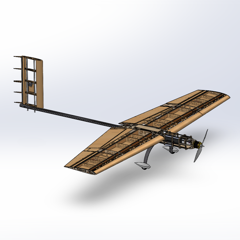
UTDallas 2024-25 AIAA Design/Build/Fly Competition Submission
Neonatal Lumbar Puncture Assistance Device
Silicone-Based PneuNet Robot
Team CAD Project
[Personal Interest Project]
[Woodworking Project]
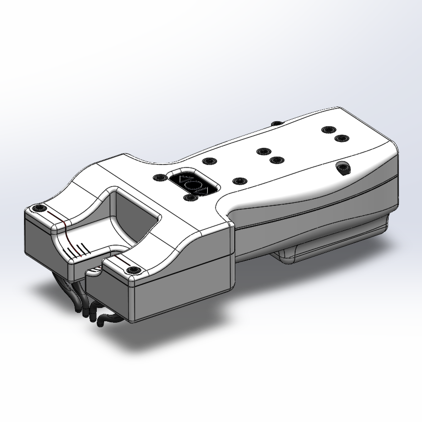
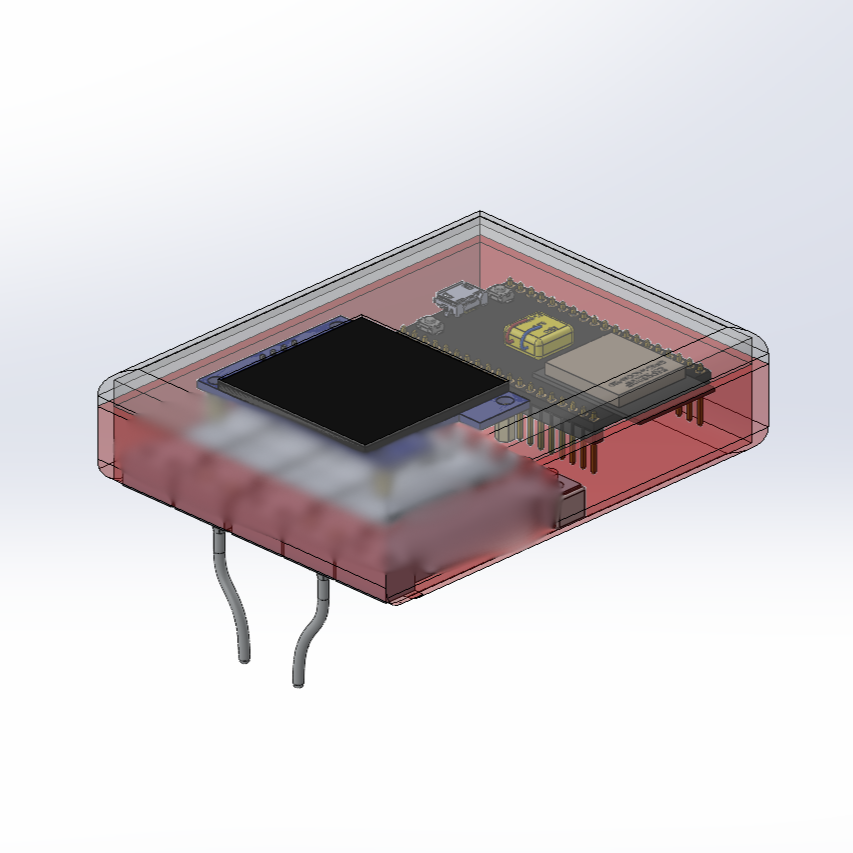
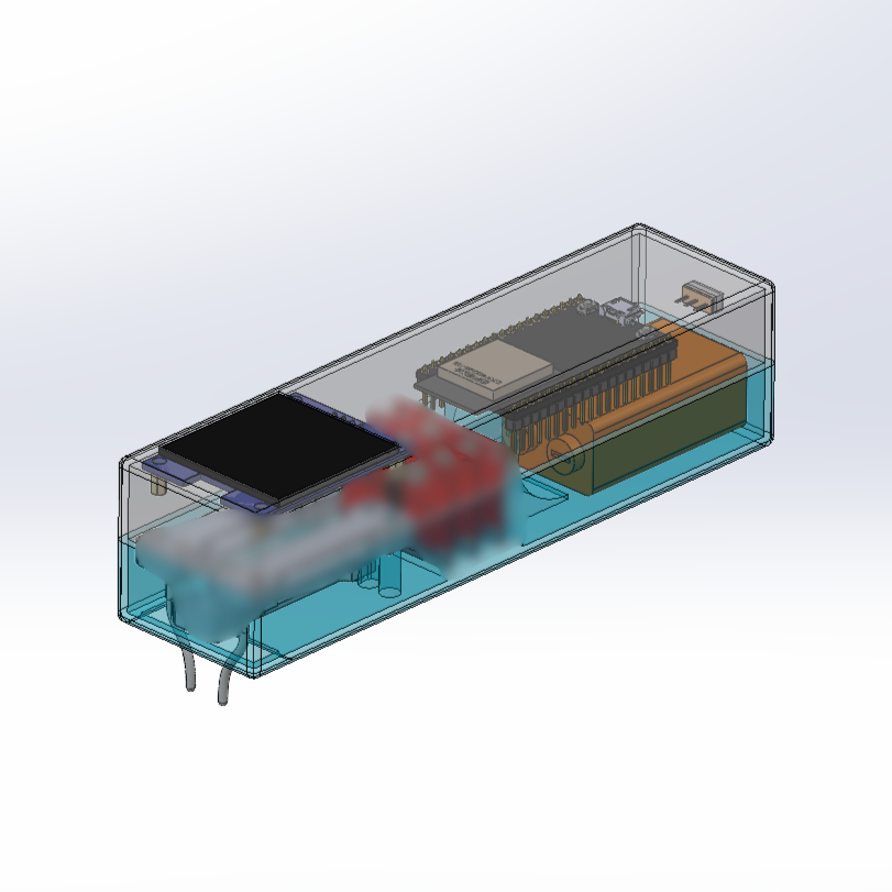
NeoTap (previously known as Wavy Baby) is the result of my capstone project during my undergrad at UT Dallas. My team and I developed this device from early problem definition and conception through prototyping, iteration, and final design.
I completely owned the design and configuration of the device, and also determined force-measuring probes as the best detection modality for our requirements and constraints. Along with technical work, I also managed regular communication with the client, mentor, and capstone program directors.
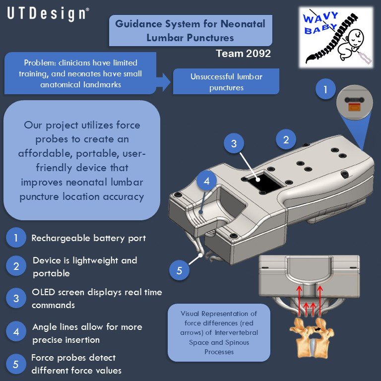
This device was designed to assist pediatric medical professionals in performing a Neonatal Lumbar Puncture, commonly known as a Spinal Tap.
The current, unassisted standard of care is inaccurate as it relies solely on the doctor's senses, and the current method of assistance is by using an ultrasound to be able to visualize the intervertebral space. These methods require extensive training, can be extremely expensive, and cause unnecessary pain to the patient if the procedure fails.
This device aims to solve these issues by offering an affordable, portable, user-friendly design that will improve the accuracy of Neonatal LP's through quantitative feedback that can be used effectively by providers with a minimal amount of training.
The device works by comparing force values measured from probes that are placed along the spine, and directs the user to move the device longitudinally along the spine until an acceptable insertion location is found within a specified threshold.
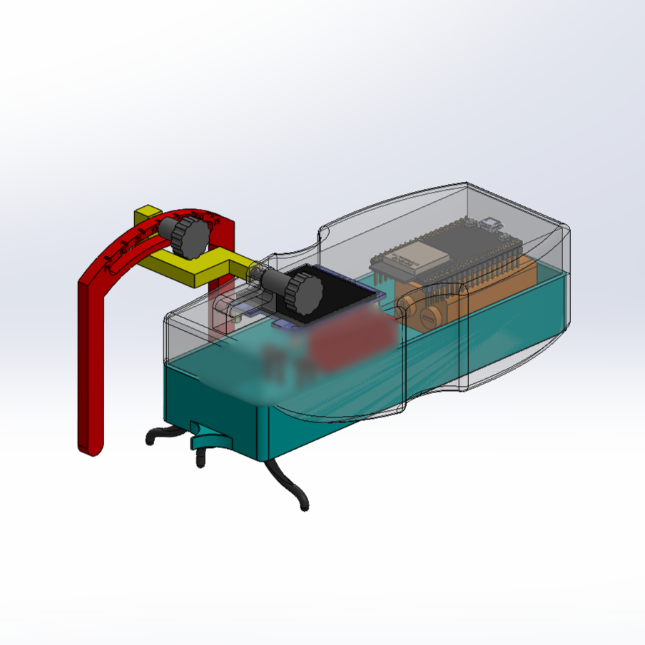
As of 2025, we are working to secure a patent for our prototype and develop our technology into a market-ready product that can be purchased by hospitals, clinics, and even individual medical providers by improving material quality, components, and configuration.
This was the final project for the Soft Robotics course where each team had full authority to decide what our project parameters, workflow, and deliverables would be. We researched existing soft robotics, common issues in the field, and developed the entire fabrication and testing process.
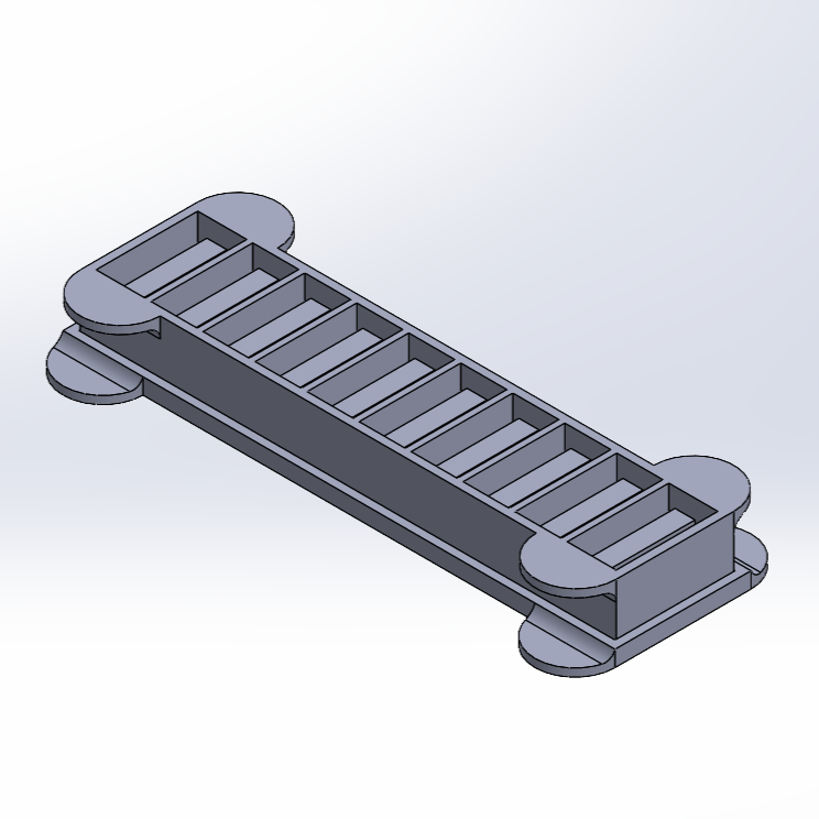
Along with my teammates, I took part in the preliminary research, testing, and compiling the report, and observed the fabrication process using EcoFlex 00-10. I completely owned the CAD design of the 3D printed mold, and received input and final confirmation from teammates.
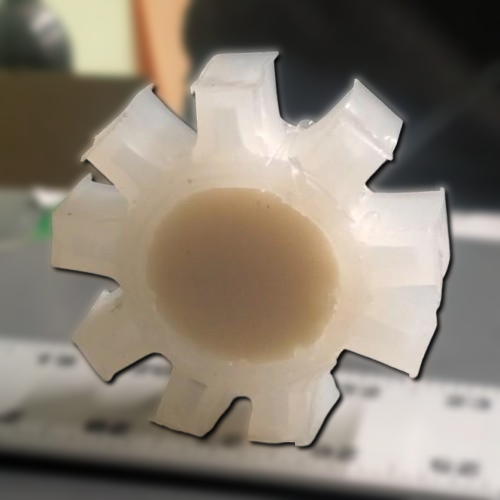
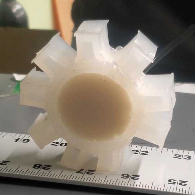
A common issue in the field of robotics is the massive impact that rigid robots leave on their surroundings because of their inelastic bodies. This project aims to navigate this challenge by presenting a soft wheel that takes advantage of the principle of PneuNets.
We will discuss an elastomer wheel composed of multiple individual chambers around the circumference that sequentially inflate and deflate to induce rotational motion. The wheel will be non-disruptive and be able to conform to its terrain, resulting in better maneuverability. While the working concept behind this soft robot is relatively simple, it offers a look into the possibilities of locomotion in the future of the field of robotics.
Our 3 major design considerations were:
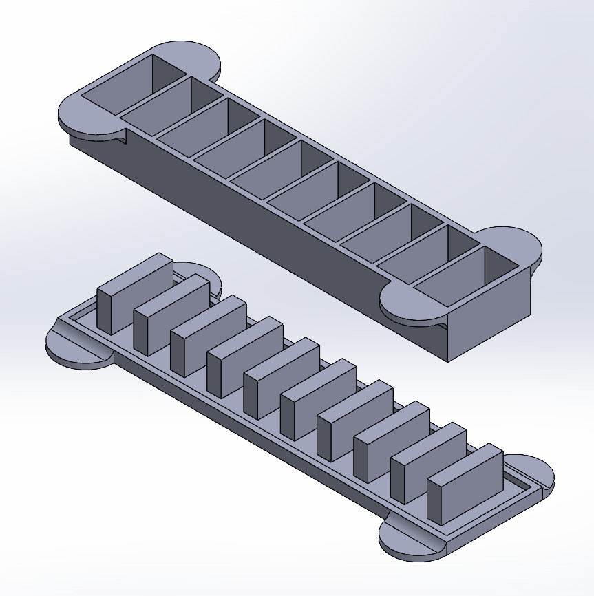
The CAD design is of the tested mold consisting of 10 chambers that are independant of one another once joined around the circumference of the wheel's center.
After the walls on the chambers popped due to excess air pressure, we iterated the design settled on a wall thickness that made the chambers more durable without causing the wheel to be too heavy to roll.
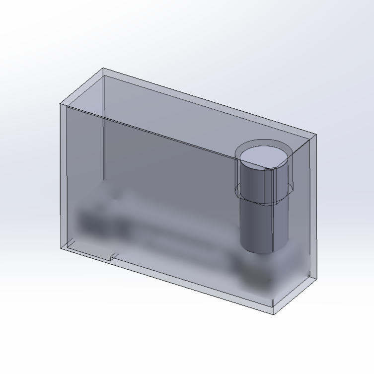
We tested our design by poking a small hole in the side of one of the chambers to attach an air pressure valve for actuation. A range of pressures were tested to determine how much is needed to roll the wheel to the next chamber. While this approach worked at lower pressures, the air would leak at higher pressures. We solved this by adding a clamp with a small amount of EcoFlex around the edges of the hole to seal the gap around the valve. Once the pressure range was determined, a ruler was used to measure the distance travelled in one roll depending on the pressure used.
After confirming the viability of the design, we automated the actuation process by using an Arduino and L298N motor driver. This driver controls the how much pressure is released into the chamber, how long the pressure is applied, and the timing between actuations.
Actuation Pressure Range: 5 - 15 psi
Distance Travelled per Actuation: 1.5 - 2.25 inches
While this test was conducted using one air chamber, it can be applied to multiple using a sequential actuation by connecting an individual air pressure valve and solenoid to each chamber.